Project Overview
This project supports Dr. Aristides Kiprakis’ SquidROV by granting it wireless communication abilities and was supervised by him. This first iteration was successfully prototyped for dry-land use, but is designed with waterproofing in mind, and the report details suggestions for progression. The Pointing and Tracking Device for Bidirectional Laser Communication (PATBLC) performed well, with a link-closing time of 0.23s/60-degrees and $85\%$ accuracy over 20 trials for a target situated 500mm from the end-effector. Accuracy over various distances could not be measured due to noise limitations as well as the lack of a second system as only one camera was received. Some of the future-work recommendations include the implementation of an instrumentation amplifier for measurement noise reduction, and the use of a more powerful controller to extend the target identification range beyond the current 870mm.This project was programmed using LabVIEW on the same myRIO that actuates the SquidROV.
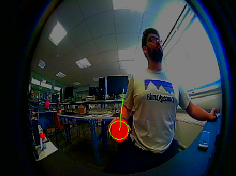
The video below shows successful data transmission and accurate tracking.
The beginning of the video shows the PATBLC tracking the object from Quadrant 1 to Quadrant 2 (explained in the IK section). Next, the it shows successful data transmission via laser. Finally, it shows me controlling the system with my mouse.
Computer Vision
The computer vision pipeline starts by applying a color-threshold in the RGB space to draw-out the red circular target mounted to each PATBLC. After this, a 3x3 Gaussian Blur to smooth particle edges, which speeds up subsequent processes. A small kernel was used to maintain a high frame-rate. Next, a Heywood Circularity Particle Filter is applied, which detects circularity in particles grouped by either 4 or 8-pixel connectivity frames. If a particle is deemed non-circular, it is removed from the processed image, where circularity is assessed using $HCPF = \frac{P}{2 \sqrt{\pi A}}$, where $P$ and $A$ are the particle’s perimeter and area respectively. Then, after eliminating too-small elements using a series of erosions and dialations, the image is ready for elliptical shape detection.
Shape detection is performed by first finding curve seed points in the image. For each unique seed, a curve is traced by adding neighboring pixels with qualifying edge thresholds in both directions away from the seed until termination; if there are no more qualifying pixels in a given direction. Traced curves with ends in close proximity are then stitched together, whereas curves with open ends or which are composed of three pixels or less, are removed.
Finally, the resultant closed curve is compared to an Elliptical template for varying major and minor axes, and a score is returned. If the score is above a perscribed threshold, the shape detection is deemed successful, and the centroid of each detected ellipse is returned. Ideally, we only want one detected Ellipse in the processed image, but in case there are many, only the centroid of the highest scoring one is returned and a circle with the minor axis radius is traced for visual confirmation. A Kalman Filter with a particle motion model is then applied to the tracked object for better dynamic detection.
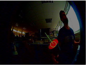
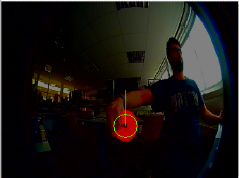
The results are shown below for ideal conditions, low light, skew, and occlusion:
Inverse Kinematics & Control
The system is comprised of 3D printed components whose links are actuated by perpendicular revolute joints via servo motors which allow it to achieve a half-spherical workspace at the end-effector. Inverse Kinematics is implemented to control the restricted motors by flipping the end-effector for one quarter-sphere of the workspace. An ease-out function is used to dampen the motors’ response near their commanded targets as the MG996R servos used - while cost-effective - produced too much torque for the weight of the system.
The Inverse Kinematics for this system was developed heuristically, and divided into four discontinuous quadrants, each of which has an identical counterpart with a different entry point into said quadrant:
- Quadrant 1:1, Azimuth <= $\pi$, Elevation <= $\pi/2$.
- Quadrant 1:2, Azimuth > $\pi$, Elevation > $\pi$.
- Quadrant 2:1, Azimuth > $\pi$, Elevation <= $\pi/2$.
- Quadrant 2:2, Azimuth <= $\pi$, Elevation > $\pi/2$.
Essentially, the :1 versions of quadrants are entered from an Azimuth breach, whereas the :2 versions are entered via an Elevation breach. The details are expanded in the report.
Ultimately, this causes the end-effector to flip for one half of the workspace, surmounting the servo motors’ 180-degree limitation to continue tracking for the entire half-spherical workspace.
Optics
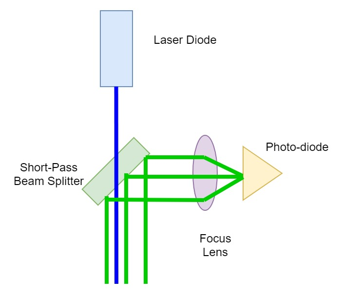
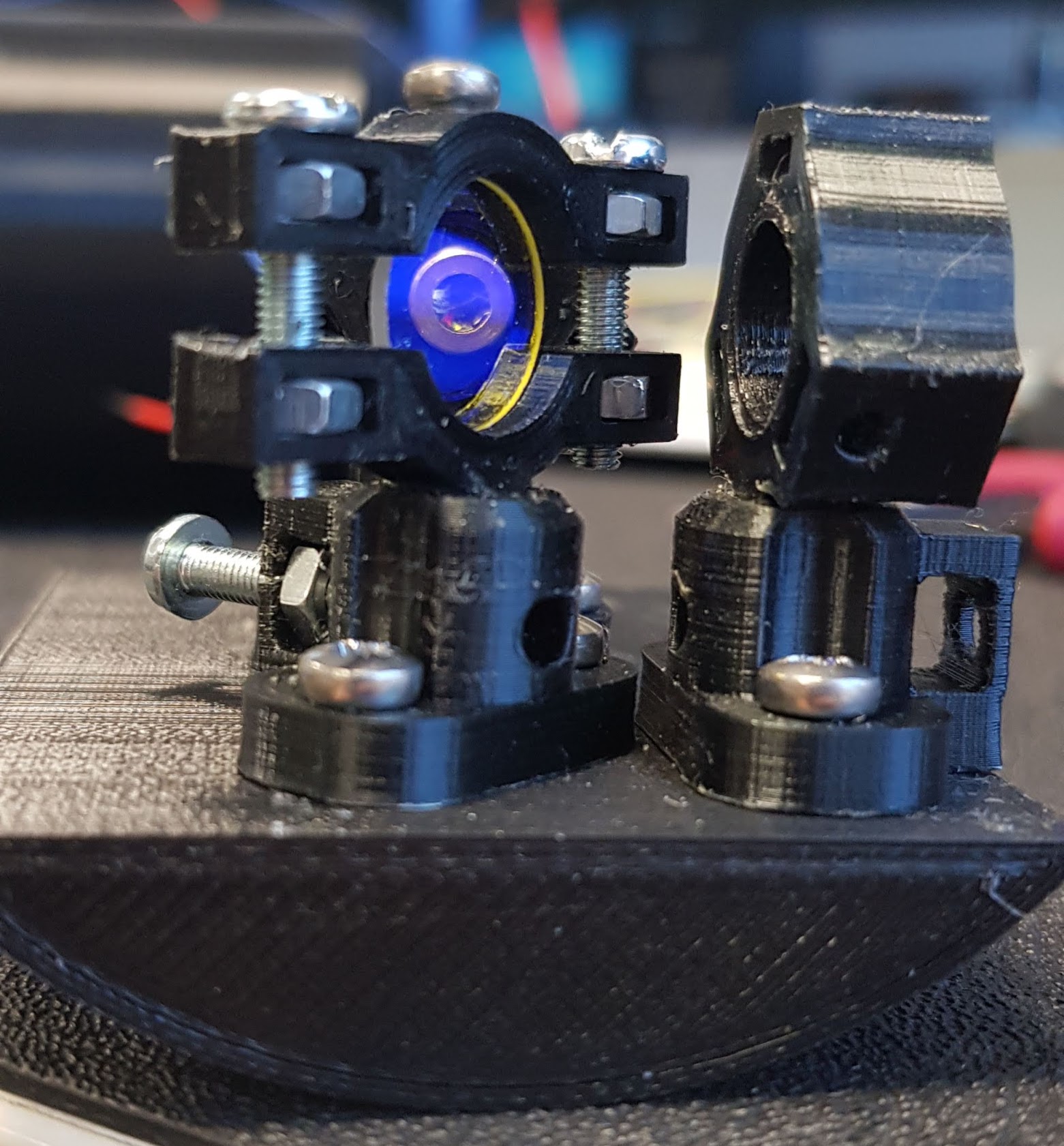
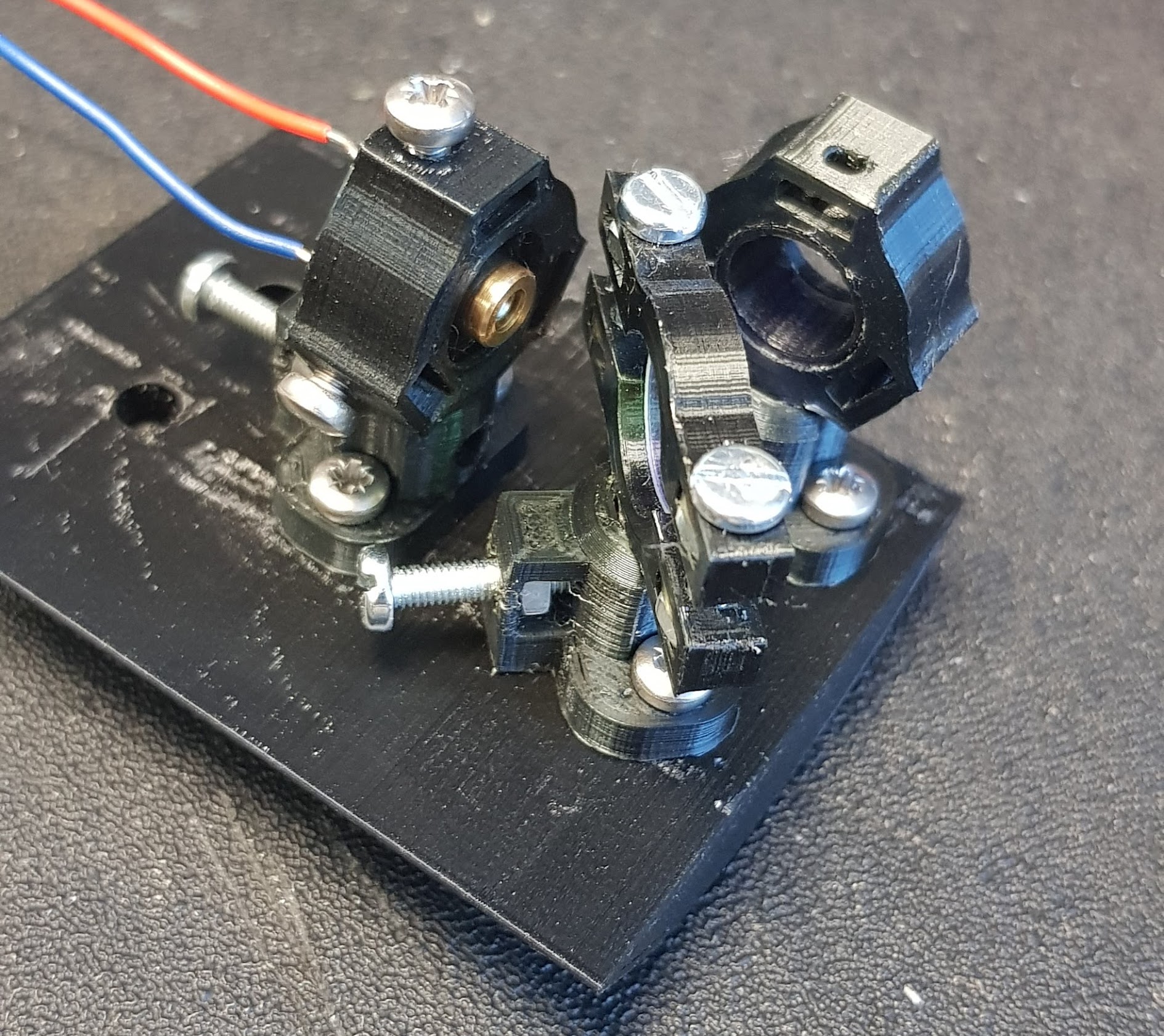
The End-Effector houses an optical breadboard carrying a laser, a dichroic mirror, a focus lens and a receiver - although the focus lens was not received for this prototype. The system sending the blue laser houses a short-pass dichroic mirror to pass its own beam out of the End-Effector and to reflect its twin system’s beam onto its photodiode receiver for data reception. The alternate system uses a long-pass dichroic mirror and a red beam. A green beam was originally intended, but it was not possible to find one below the laser class III, which is unsuitable for un-enclosed use at the university.
The diagram below shows the optical setup as well as a finished optical breadboard, which is inverted with a long-pass beam splitter for the twin device:
The report goes into much more detail on these topics, check it out below!