Project Showcase
Here’s a video of the final product! I had to steer away from the instructions a little bit (explained below) to allow my pan-tilt camera to follow the ball for a full 360-degree pan. The gif below shows the way I achieve this, by flipping the camera upside-down for the second half of the motion. For more information, here’s an article by the Master of Science in Robotics newsletter!

Day 1: Movement
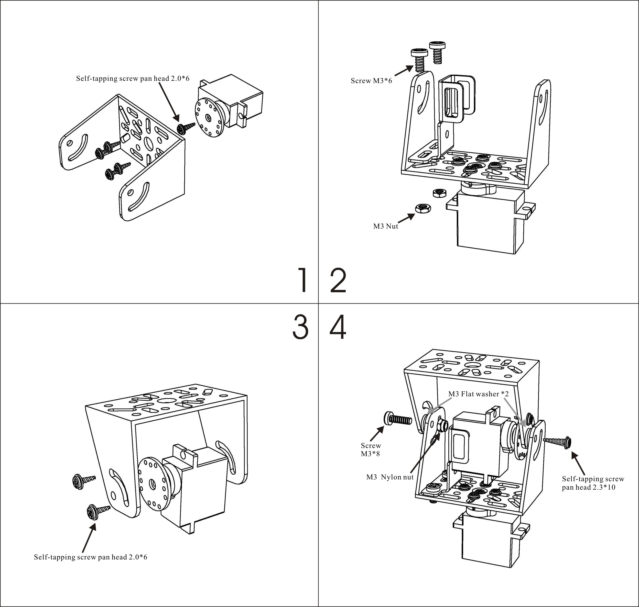
The first task of the day was to solder the connector pins for the provided Micro-Maestro Pololu board, used to control the provided servo motors. Next, we each assembled our own pan-tilt camera mount using these instructions. I deviated on steps 3 and 4 by purposefully not fastening the screws in the provided tracks, which only allow for 90-degree motion for the tilt servo. My setup allows for 180 degrees of rotation for each motor, and hence for a half-spherical field of view for the mounted camera.
Finally, we wrote some basic code to control the motors using Pulse-Width-Modulated (PWM) signals converted from degrees as per user input at the terminal.
Day 2: Vision
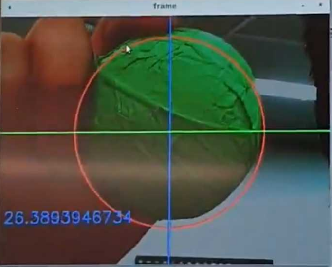
This day was focused on object tracking. We used this guide, which provided links to OpenCV documentation. For my implementation, I thresholded my image in the green HSV space and used image moments and contour detection to find the centroid of the tracked object after applying a 3x3 Gaussian Kernel Blur and a few erosions and dialations (dialations simply restore the eroded image without restoring eliminated nose) to clean up the feed and speed up object recognition. I was able to achieve object recognition at around 27FPS, which is good enough for real-time tracking.
Day 3: Control
On the last day, we put everything together! The first part of my task was to perform a camera calibration to extract the tracked object’s heading relative to the centre of the camera. To do this, I measured the size of the object, and recorded its pixel radius at various distances away from the camera to create a map between the object’s pixel radius and its distance away from the camera. From this, I extracted the pan heading from the tangent inverse of the object’s x-distance from the camera centre and its distance away from the camera. Similarly, the tilt heading was acquired from the tangent inverse of the object’s y-distance from the camera centre and its distance away from the camera. This is a more complicated procedure than a pixel-space based PID controller, but achieves the half-spherical tracking space I mentioned earlier.
Next, the camera’s current orientation is derived using fairly simple Forward Kinematics, and the object’s offset is added to these pan and tilt values. Using this information, I then calculate one of four quadrants the object could be in and send the appropriate joint angles to orient the camera accordingly. The result can be seen in the gif at the top of this post. The resultant behaviour has the camera working in two main modes: standard, and inverted. You’ll notice in the gif above that the first half of the motion tracking is done with an upright camera orientation, but when I move the ball into the other half of the expanded workspace, the camera flips upside down to keep following the object, and then flips again to re-enter the first half of the workspace.
Learning Outcomes
Overall, this hackathon was a great opportunity for me to collaborate with my future classmates! We learned a lot from each other and were able to get to know each other. I really enjoyed seeing the different ways people completed the task, as almost no two were the same! I hope you enjoyed this post. Unfortunately, I can’t share the code as it is possible that the same project may be used for future hackathons. Please contact me if you would like a copy of the code.